Installation Methods for Sheath Heating Cables
This is the excerpt for the preview and the preview text at the top
Hi, from Stapelfeld.
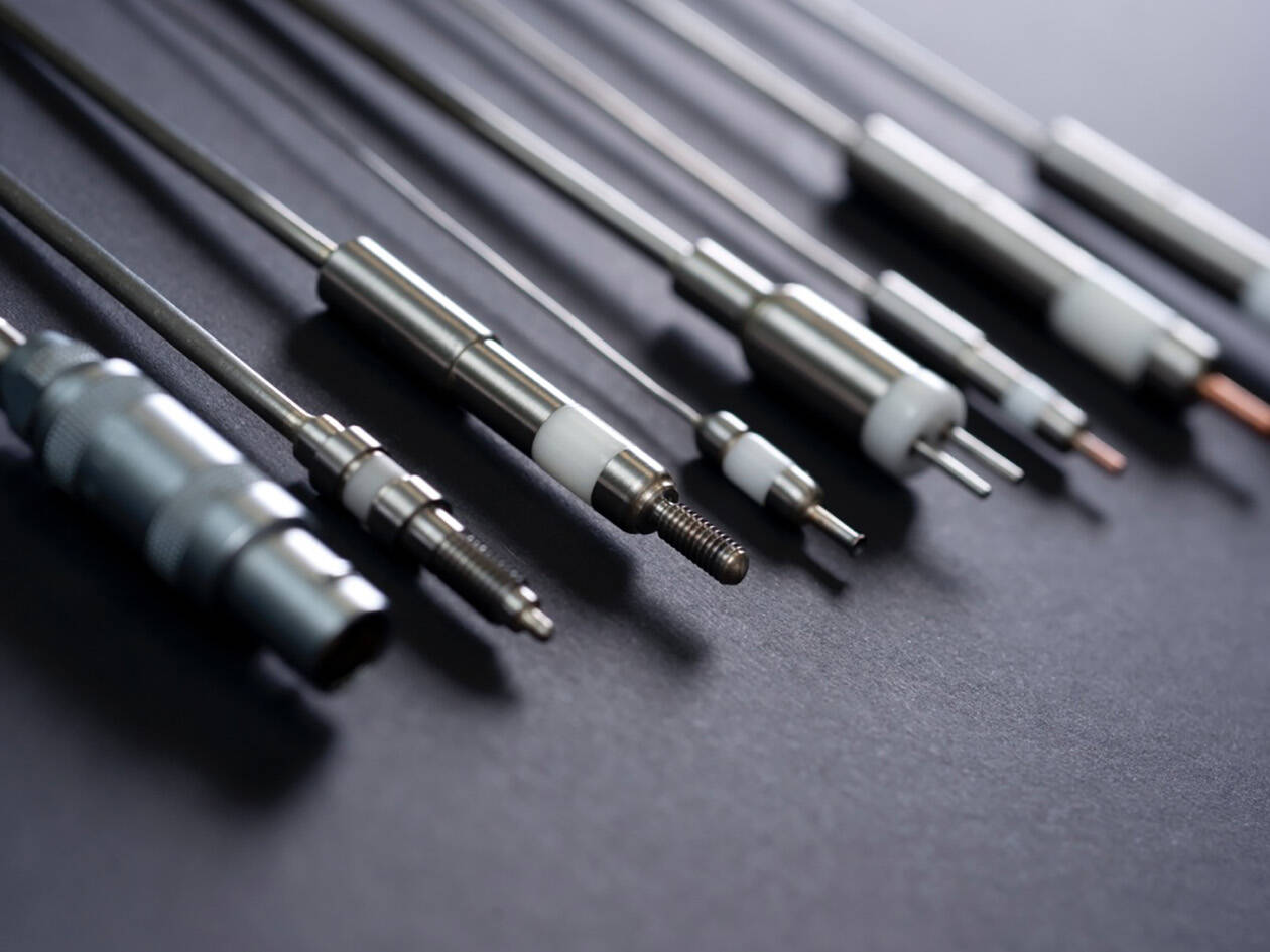
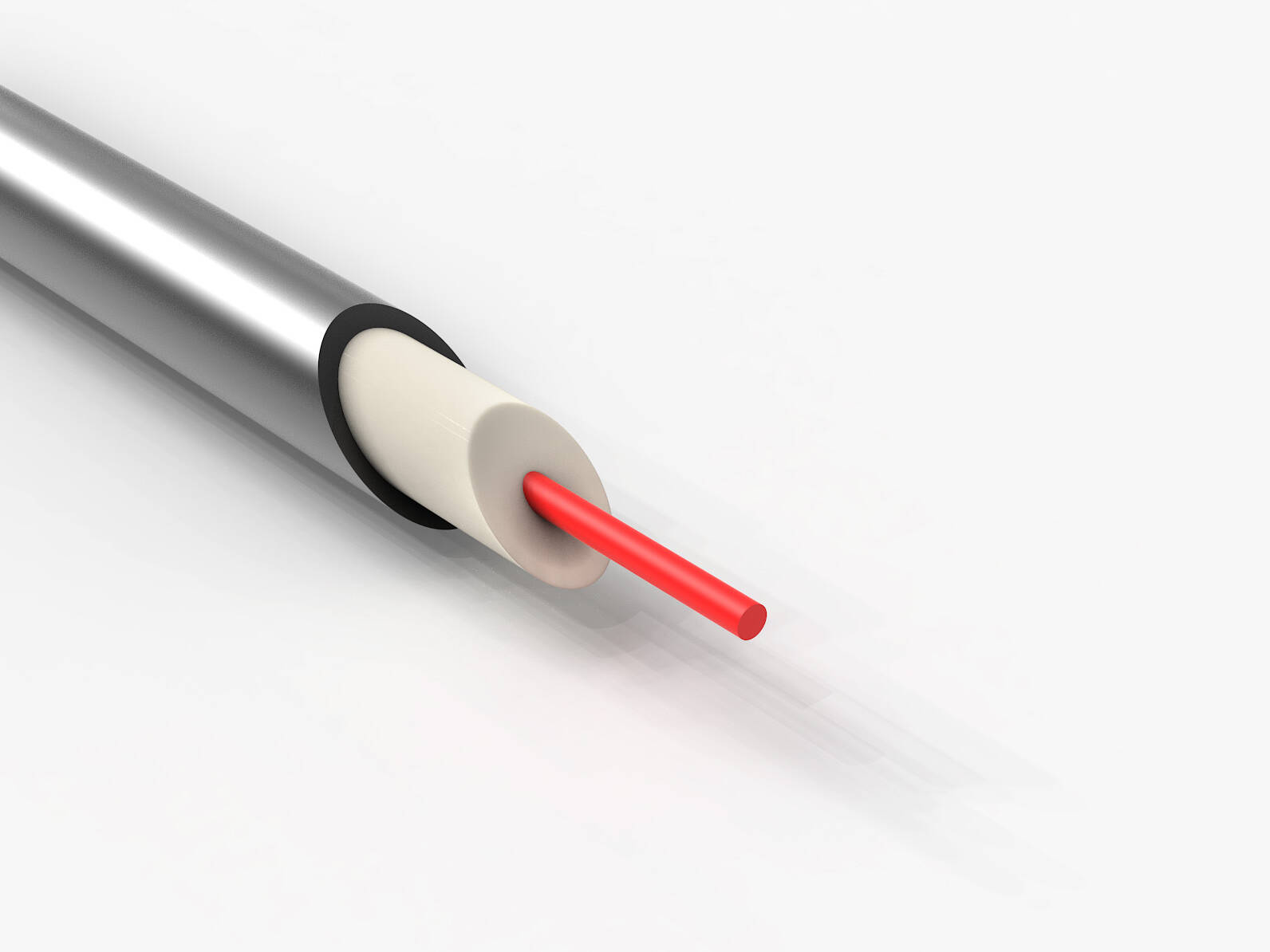
The heating power that a sheathed heating conductor can safely transmit depends largely on the installation method. The better the thermal contact with the component to be heated, the higher the power density can be. The following tables show the recommended power ranges for four different heating conductor diameters with various installation methods.
Installation Methods for Sheathed Heating Cables:
 |
 |
 |
 |
|
 |
 |
 |
 |
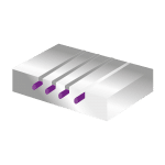
Explanation of the installation methods:
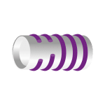
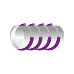
Installation Methods 1–4: Easy installation by winding, securing with metal strips, or spot welding. Suitable for low heating capacities up to approximately 100 W/m.
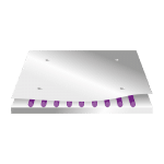
Installation Type 5-7: Secure thermal contact achieved by inserting into grooves, brazing, or clamping between plates. Suitable for medium heating capacities up to approximately 300 W/m.
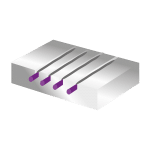
Mounting Method 8-9: Optimal heat transfer through soldering into grooves or embedding in metal. Suitable for high heating outputs exceeding 300 W/m.
Heatsealing band 1.0 mm
Resistance/m at 20°C - Bending radius 2-3 x outer diameter
| Order designation | Outer diameter ±0.08 mm |
Heating element ± 10% |
Cold part | Ω/m ± 10% |
Mounting type 1-4 | Mounting type 5-7 | Mounting type 8-9 | |||
|---|---|---|---|---|---|---|---|---|---|---|
| Max. permissible voltage | Performance | Max. permissible voltage | Performance | Max. permissible voltage | Performance | |||||
| SMH-I10/250 | 1 | 250 | >500 | 12,50 | 9V | 25 W | 12 V | 45 W | 15 V | 75 W |
| SMH-I10/500 | 1 | 500 | >500 | 18,00 | 18 V | 50 W | 24 V | 95 W | 30 V | 145 W |
| SMH-I10/750 | 1 | 750 | >500 | 30,00 | 30 V | 100 W | 40 V | 170 W | 48 V | 245 W |
| SMH-I10/1000 | 1 | 1000 | >500 | 40,00 | 40 V | 130 W | 50 V | 200 W | 60 V | 285 W |
| SMH-I10/2000 | 1 | 2000 | >500 | 70,00 | 70 V | 196 W | 90 V | 324 W | 115 V | 530 W |
Heatsealing band 1.5 mm
| Order designation | Outer diameter ±0.08 mm |
Heating element ± 10% |
Cold part | Ω/m ± 10% |
Mounting type 1-4 | Mounting type 5-7 | Mounting type 8-9 | |||
|---|---|---|---|---|---|---|---|---|---|---|
| Max. permissible voltage | Performance | Max. permissible voltage | Performance | Max. permissible voltage | Performance | |||||
| SMH-I15/500 | 1,5 | 500 | >500 | 5,5 | 15 V | 80W | 20 V | 140 W | 25 V | 225 W |
| SMH-I15/1000 | 1,5 | 1000 | >500 | 5,5 | 30 V | 165 W | 40 V | 290 W | 50 V | 455 W |
| SMH-I15/1500 | 1,5 | 1500 | >1000 | 5,5 | 45 V | 250 W | 60 V | 440 W | 75 V | 685 W |
| SMH-I15/2000 | 1,5 | 2000 | >1000 | 5,5 | 60 V | 330 W | 80 V | 580 W | 100 V | 910 W |
| SMH-I15/3000 | 1,5 | 3000 | >1000 | 5,5 | 90 V | 495 W | 125 V | 950 W | 150 V | 1350 W |
| SMH-I15/4000 | 1,5 | 4000 | >1000 | 5,5 | 120 V | 660 W | 150 V | 1050 W | 150 V | 1050 W |
Heatsealing band 2.0 mm
| Order designation | Outer diameter ±0.08 mm |
Heating element ± 10% |
Cold part | Ω/m ± 10% |
Mounting type 1-4 | Mounting type 5-7 | Mounting type 8-9 | |||
|---|---|---|---|---|---|---|---|---|---|---|
| Max. permissible voltage | Performance | Max. permissible voltage | Performance | Max. permissible voltage | Performance | |||||
| SMH-I20/500 | 2 | 500 | >500 | 3,1 | 12 V | 90 W | 18 V | 205 W | 22 V | 300 W |
| SMH-I20/1000 | 2 | 1000 | >500 | 3,1 | 25 V | 210 W | 35 V | 410 W | 42 V | 590 W |
| SMH-I20/1500 | 2 | 1500 | >1000 | 3,1 | 40 V | 340 W | 55 V | 645 W | 65 V | 900 W |
| SMH-I20/2000 | 2 | 2000 | >1000 | 3,1 | 50 V | 440 W | 70 V | 790 W | 85 V | 1150 W |
| SMH-I20/3000 | 2 | 3000 | >1000 | 3,1 | 80 V | 690 W | 110 V | 1300 W | 130 V | 1820 W |
| SMH-I20/4000 | 2 | 4000 | >1000 | 3,1 | 110 V | 970 W | 140 V | 1570 W | 175 V | 2450 W |
| SMH-I20/5000 | 2 | 5000 | >1000 | 3,1 | 130 V | 1100 W | 180 V | 2075 W | 200 V | 2560 W |
| SMH-I20/6000 | 2 | 6000 | >1000 | 3,1 | 155 V | 1300 W | 210 V | 2370 W | 230 V | 2850 W |
| SMH-I20/7000 | 2 | 7000 | >1000 | 3,1 | 180 V | 1500 W | 230 V | 2450 W | 230 V | 2450 W |
| SMH-I20/8000 | 2 | 8000 | >1000 | 3,1 | 210 V | 1750 W | 230 V | 2100 W | 230 V | 2100 W |
Heatsealing band 3.0 mm
| Order designation | Outer diameter ±0.08 mm |
Heating element ± 10% |
Cold part | Ω/m ± 10% |
Mounting type 1-4 | Mounting type 5-7 | Mounting type 8-9 | |||
|---|---|---|---|---|---|---|---|---|---|---|
| Max. permissible voltage | Performance | Max. permissible voltage | Performance | Max. permissible voltage | Performance | |||||
| SMH-I30/5000 | 3 | 5000 | >1000 | 1,4 | 110 V | 1730 W | 145 V | 3000 W | 180 V | 4630 W |
| SMH-I30/8000 | 3 | 8000 | >1000 | 1,4 | 170 V | 2640 W | 230 V | 4700 W | 290 V | 7500 W |
| SMH-I10/10000 | 3 | 10000 | >1000 | 1,4 | 230 V | 3780 W | 290 V | 6000 W | 300 V | 6400 W |
Custom Configurations
Heating and cooling sections can be freely defined to precisely tailor the heating capacity to your application. Custom designs are available even for small quantities.
| Jacket material | Diameter (mm) | Minimum length of heating element (mm) | Resistance of the heating element (Ω/m) | Resistivity of the cold section (Ω/m) |
|---|---|---|---|---|
| Stainless steel 1.4541, Inconel 600 | 1,0 | 250 | 12,5 | < 1,3 |
| Stainless steel 1.4541, Inconel 600 | 1,5 | 250 | 5,5 | < 0,6 |
| Stainless steel 1.4541, Inconel 600 | 2,0 | 250 | 3,1 | < 0,3 |
| Stainless steel 1.4541, Inconel 600 | 3,0 | 250 | 1,4 | < 0,2 |
Tolerances: Outer diameter +/- 0.08 mm, length tolerance of heating element +/- 10%, resistance +/- 10%.
Conclusion: Maximum flexibility with minimal space requirements
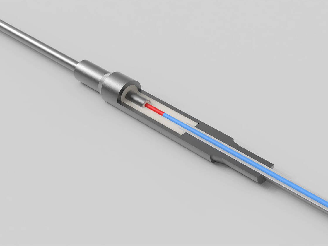
Sheath heating wires with seamless cold ends are the ultimate solution for complex heating tasks in the tightest of spaces. Their seamless construction and high flexibility make them an indispensable tool for engineers developing innovative and space-saving heating solutions. With a total of 24 different product variants and four diameters (1.0 mm to 3.0 mm), they cover a power range from 25 W up to an impressive 7,500 W. The power tables clearly show how the choice of mounting method influences the maximum power density—a crucial factor in the design of your heating solution.
Other connection options are available.
Please feel free to contact us!
More information that might interest you
Connections, Installation, and Quality Assurance: From Heating Cables to Reliable Heating Solutions.
This is the excerpt for the preview and the preview text at the top
0 Comments5 Minutes
Mineral-insulated sheathed heating cables with attached, seamless cold ends
Mineral-insulated heating cables without cold ends can be used reliably up to about 400 °C. If…
0 Comments9 Minutes
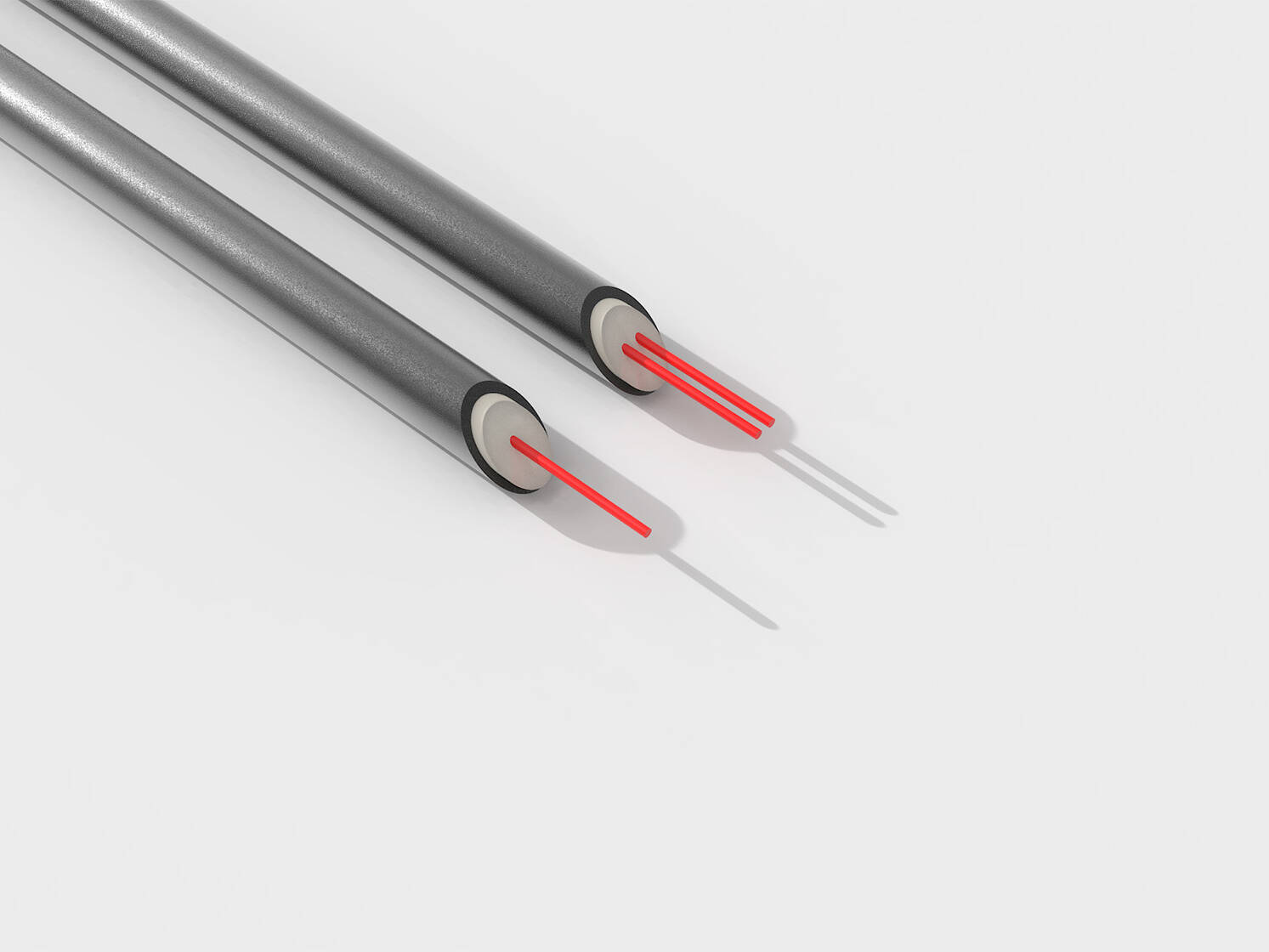
Single- and two-conductor sheathed cables: The foundation for your heating solution.
Mineral-insulated sheathed heating cables—single-conductor or twin-conductor? This fundamental decision…
0 Comments9 Minutes
Mineral-Insulated Sheathed Heating Cables: Technical Guide for Technicians & Engineers.
In demanding industries such as aerospace, semiconductor technology, and high-end mechanical engineering…
0 Comments10 Minutes
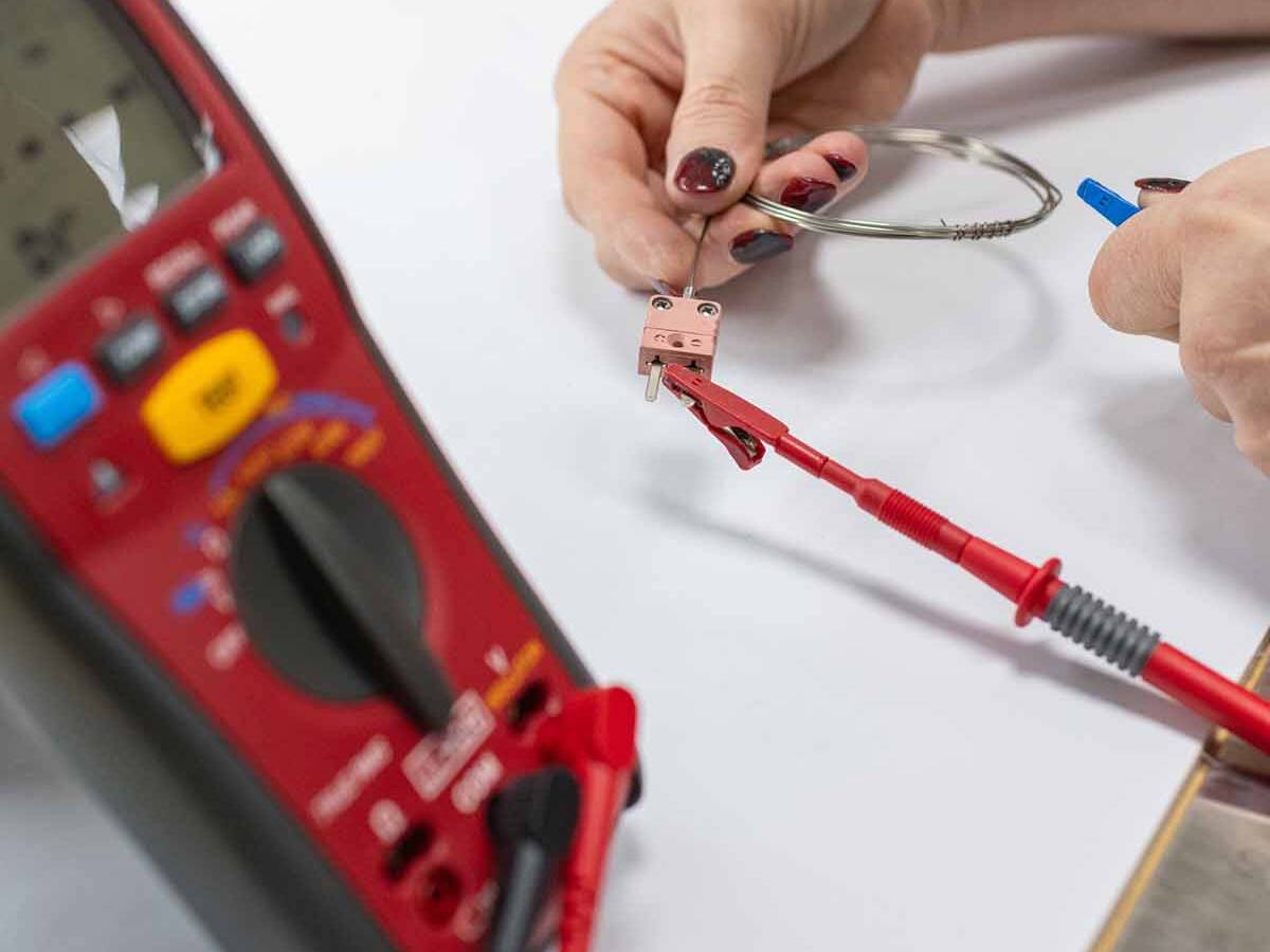
How to Calibrate a Thermocouple Correctly – A Practical Guide.
How to Calibrate Thermocouples Correctly! A practical guide with methods, tips, and…
0 Comments6 Minutes
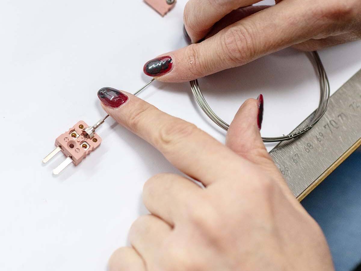
How to Choose the Right Thermocouple – A Guide for Industry.
Which Thermocouple Is Right for You? A Practical Guide to Types, Materials, &…
0 Comments7 Minutes
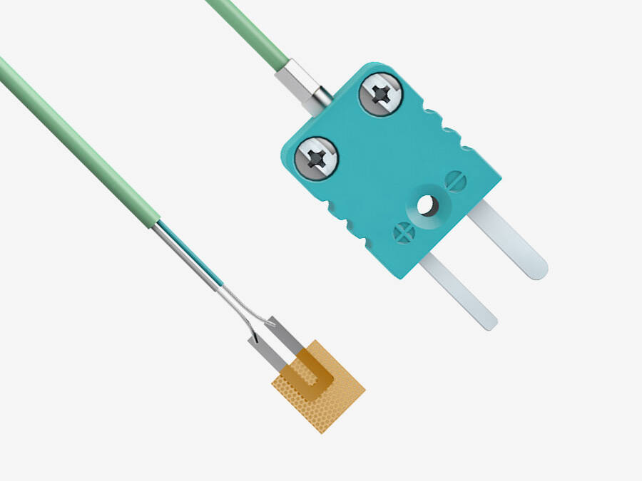
Focus on Thermocouples – Why Precise Temperature Measurement Is Important.
Accurate temperature measurement is not just an option—it is essential. Thermocouples are far…
0 Comments5 Minutes