Mineral-insulated sheathed heating cables with attached, seamless cold ends
Mineral-insulated sheathed heating cables without cold ends can be used reliably up to about 400 °C. However, if the application requires higher power ratings or process temperatures up to 1000 °C, sheathed heating cables with cold ends are essential. They ensure that the heated area remains clearly defined and that the connection zones are kept cool and safe.
This article presents the two available designs: jacket heating wires with transition sleeves and attached cold ends—ideal when heating and cold zones must be precisely separated—as well as seamless cold ends, in which the resistance change occurs internally and the outer diameter remains completely uniform. The latter offer maximum flexibility, high temperature resistance, and are suitable for applications up to 1000 °C, tight bend radii, or use in a vacuum. In addition to the design, operating principle, and advantages of both variants, you’ll receive an overview of available standard types, technical data, mechanical and thermal limits, as well as guidelines for proper design and installation. This provides you with a solid basis for selecting the right heating solution.
Hi, from Stapelfeld.
Due to its connection type, a mineral-insulated sheathed cable without cold ends can generally be used at temperatures up to 400°C. If higher power levels and temperatures up to 1000°C are required in the process or application, the use of mineral-insulated sheathed heating cables with cold ends is recommended.
There are essentially two types: mineral-insulated sheathed heating cables with transition sleeves and attached cold ends, and mineral-insulated sheathed heating cables with seamless cold ends.
Design and Key Benefits of Mineralized Sheath Heating Cables.
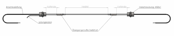
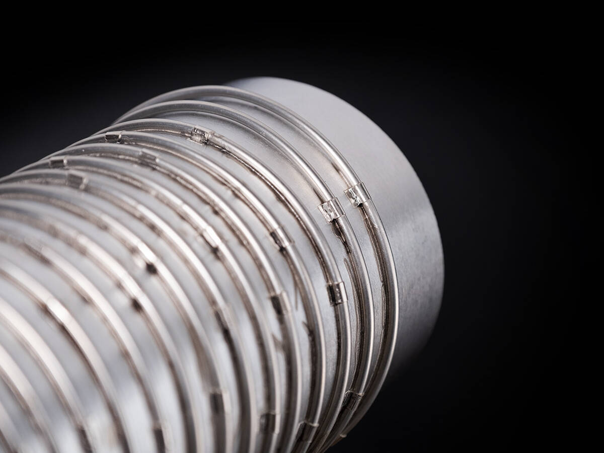
Mineral-insulated sheathed heating cable consists of a live inner conductor (heating wire) that is insulated from the metal sheath with magnesium oxide. A vacuum-compatible and temperature-resistant transition sleeve, which is welded to the heating cable and the cold ends, is used to secure the cold ends to the heating cable. It causes a slight increase in the outer diameter.
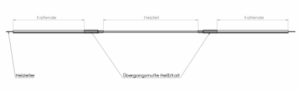
Structure of a heating conductor with attached cold ends
Mineral-insulated sheathed heating cables with attached cold ends.
When it comes to precisely defining the length of a heating element on a jacket heating conductor, jacket heating conductors with transition sleeves and attached cold ends are the first choice. This design is the solution for demanding applications where the transition from the heated to the unheated area must be clearly defined—for example, in vacuum chambers, trace heating systems, or heating ovens.
Design and Operating Principle:
The Transition Sleeve Makes All the Difference
At the heart of this design is a vacuum-compatible and temperature-resistant transition sleeve that gas-tightly welds the heating conductor and the cold conductor together. This enables a clear separation of the zones and high temperature stability of up to 600°C. Sheath heating elements with transition sleeves and attached cold ends are robust and widely used solutions for a wide range of industrial heating applications.
Application Focus:
Can be configured as a single-core jacket heating conductor with attached cold ends. Ideal for trace heating, vacuum, and high-temperature applications up to 600°C where a precise, process-reliable separation of the heating and cold zones is required. The robust, welded connection ensures reliability.
Attached cold ends
– Advantage: More cost-effective to manufacture, precise definition of the heating element length, temperature applications up to 600°C. Can be implemented as a single-core sheathed heating conductor variant.
– Disadvantage: The transition sleeve connecting the cold end to the heating conductor limits the bending radius and the transfer of heat to the component being heated. The mineral-insulated sheath heating conductor must not be bent within 30 mm before or after the transition sleeve.
Depending on the surface output and temperature requirements, special care must be taken during installation to ensure that the transition area is soldered or encapsulated so that the jacket heating conductor can transfer its heat there as well.
When used in heating plates, a separate recess must also be provided in the groove for the transition sleeve, which involves additional work. This design is particularly well-suited for use as trace heating, in vacuum and heating furnaces, as well as in standard applications with moderate mechanical requirements.
In particular, the following basic configurations are possible:
The lengths of the heated and unheated sections can be customized. The following tables show the available heating conductor options.
| Designation | Outer Diameter (mm) | Jacket material | Max. Temp. | Conductor resistance (Ω/m) |
| Stainless steel 1.4541 (up to 600°C) | ||||
| 1NICrV10 | 1,0 | Stainless steel 1.4541 | 600°C | 12 |
| 1NiCrV15 | 1,5 | Stainless steel 1.4541 | 600°C | 6 |
| 1NiCrV20 | 2,0 | Stainless steel 1.4541 | 600°C | 3 |
| 1NiCrV30 | 3,0 | Stainless steel 1.4541 | 600°C | 1,4 |
| 1NiCrV32 | 3,2 | Stainless steel 1.4541 | 600°C | 4 |
| 1NiCrV32-6 | 3,2 | Stainless steel 1.4541 | 600°C | 6,3 |
| 1NiCrV36 | 3,6 | Stainless steel 1.4541 | 600°C | 2,5 |
| 1NiCrV40 | 4,1 | Stainless steel 1.4541 | 600°C | 1 |
| 1NiCrV45 | 4,5 | Stainless steel 1.4541 | 600°C | 0,63 |
| 1NiCrV50 | 4,7 | Stainless steel 1.4541 | 600°C | 0,4 |
| Inconel 600 / 2.4816 (up to 800°C) | ||||
| 1NICrI10 | 1,0 | Inconel 600 | 800°C | 12 |
| 1NiCrI15 | 1,5 | Inconel 600 | 800°C | 6 |
| 1NiCrI20 | 2,0 | Inconel 600 | 800°C | 3 |
| 1NiCrI30 | 3,0 | Inconel 600 | 800°C | 1,4 |
| 1NiCrI32 | 3,2 | Inconel 600 | 800°C | 4 |
| 1NiCrI32-6 | 3,2 | Inconel 600 | 800°C | 6,3 |
| 1NiCrI36 | 3,6 | Inconel 600 | 800°C | 2,5 |
| 1NiCrI40 | 4,1 | Inconel 600 | 800°C | 1 |
| 1NiCrI45 | 4,5 | Inconel 600 | 800°C | 0,63 |
| 1NiCrI50 | 4,7 | Inconel 600 | 800°C | 0,4 |
| 1CuI34 | 3,4 | Inconel 600 | - | - |
Conclusion: Precision and reliability for demanding processes
Sheathed heating elements with attached cold ends are the ideal solution when precise definition of the heating section length and maximum reliability are essential. The robust transition sleeve ensures a process-reliable separation of the hot and cold zones, making this variant the top choice for demanding industrial and research applications.
Sheathed heating conductor with seamless cold ends
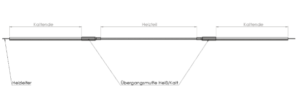
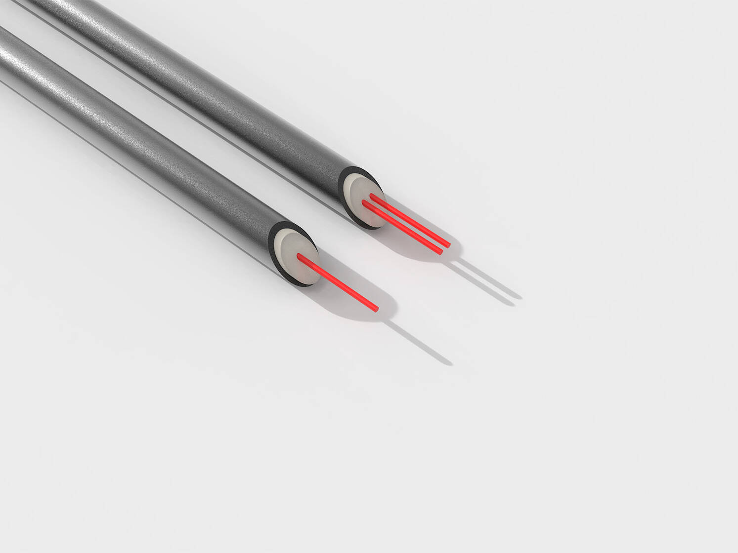
This is a real technological highlight! Here, the inner conductor consists of a single inner strand that has high resistance in the heating section and low resistance in the cold section. There are no welds or joints on the outer sheath, resulting in a uniform outer diameter along the entire length of the mineral-insulated sheath heating conductor.
Detail: Jacket heating conductor with a seamless cold end
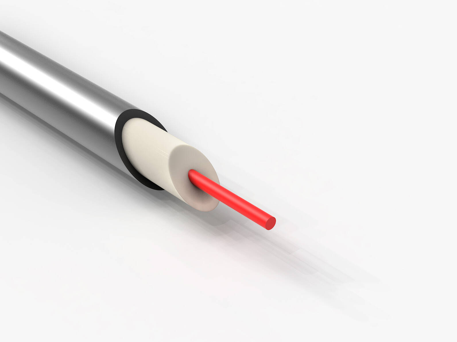
Design and Operating Principle: TheInvisible Transition
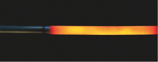
In this design, the hot/cold transition occurs internally and is not visible from the outside. As a result, the heating conductor can be bent and processed just like a standard sheathed cable, but offers the advantage of defined heating section lengths. Its high flexibility (bending radii of 2–3 times the outer diameter) and temperature resistance up to 1000°C open up a wide range of applications.
Seamless cold ends
– Advantage: Maximum mechanical stability and reliability, as there are no additional mechanical joints. This allows for a more uniform temperature distribution than with attached cold ends. The jacket heating conductor can be bent along its entire length in accordance with its bending radius. No separate recesses are required in structures or heating plates. Ideal for demanding heating applications up to 1000°C under harsh environmental conditions and in ultra-high vacuum.
– Disadvantage: More expensive to manufacture. Fixed heating element lengths; custom solutions available upon request for minimum order quantities.
For applications in the aerospace industry, in vacuum environments, or under high mechanical loads, this design is often the only safe choice. Such a solution can be custom-designed as a heating conductor to meet the specific requirements of each application.
Standard configurations.
The following table shows the power ranges for a heating conductor with an outer diameter of 1 mm for different installation methods.
Ordering Designation Heating Element (mm) Ω/m Installation Type 1-4 (Max. Power) Installation Type 5-7 (Max. Power) Installation Type 8-9 (Max. Power)
| Order designation | Heating element (mm) | Ω/m | Installation Type 1–4 (Max. Power) | Mounting Type 5-7 (Max. Power) | Mounting Type 8-9 (Max. Power) |
| SMH-I10/250 | 250 | 12,50 | 25W | 45W | 75W |
| SMH-I10/500 | 500 | 18,00 | 50W | 95W | 145W |
| SMH-I10/750 | 750 | 30,00 | 100W | 170W | 245W |
| SMH-I10/1000 | 1000 | 40,00 | 130W | 200W | 285W |
| SMH-I10/2000 | 2000 | 70,00 | 196W | 324W | 530W |
Custom Configurations
Heating and cooling sections can be freely defined to precisely tailor the heating capacity to your application. These custom solutions are available upon request, subject to minimum order quantities.
| Jacket material | Diameter (mm) | Minimum length of heating element (mm) | Resistance of the heating element (Ω/m) | Resistivity of the cold section (Ω/m) |
| Stainless steel 1.4541, Inconel 600 | 1,0 | 250 | 12,5 | < 1,3 |
| Stainless steel 1.4541, Inconel 600 | 1,5 | 250 | 5,5 | < 0,6 |
| Stainless steel 1.4541, Inconel 600 | 2,0 | 500 | 3,1 | < 0,3 |
| Stainless steel 1.4541, Inconel 600 | 3,0 | 500 | 1,4 | < 0,2 |
Tolerances: Outer diameter +/- 0.10 mm, length tolerance of heating element – 10%, resistance +/- 10%.
Conclusion: Maximum flexibility with minimal space requirements
Heating cables with seamless cold ends are the ultimate solution for complex heating tasks, high temperatures, and applications in confined spaces and with tight radii. Their seamless construction and high flexibility make them an indispensable tool for engineers developing innovative and space-saving heating solutions.
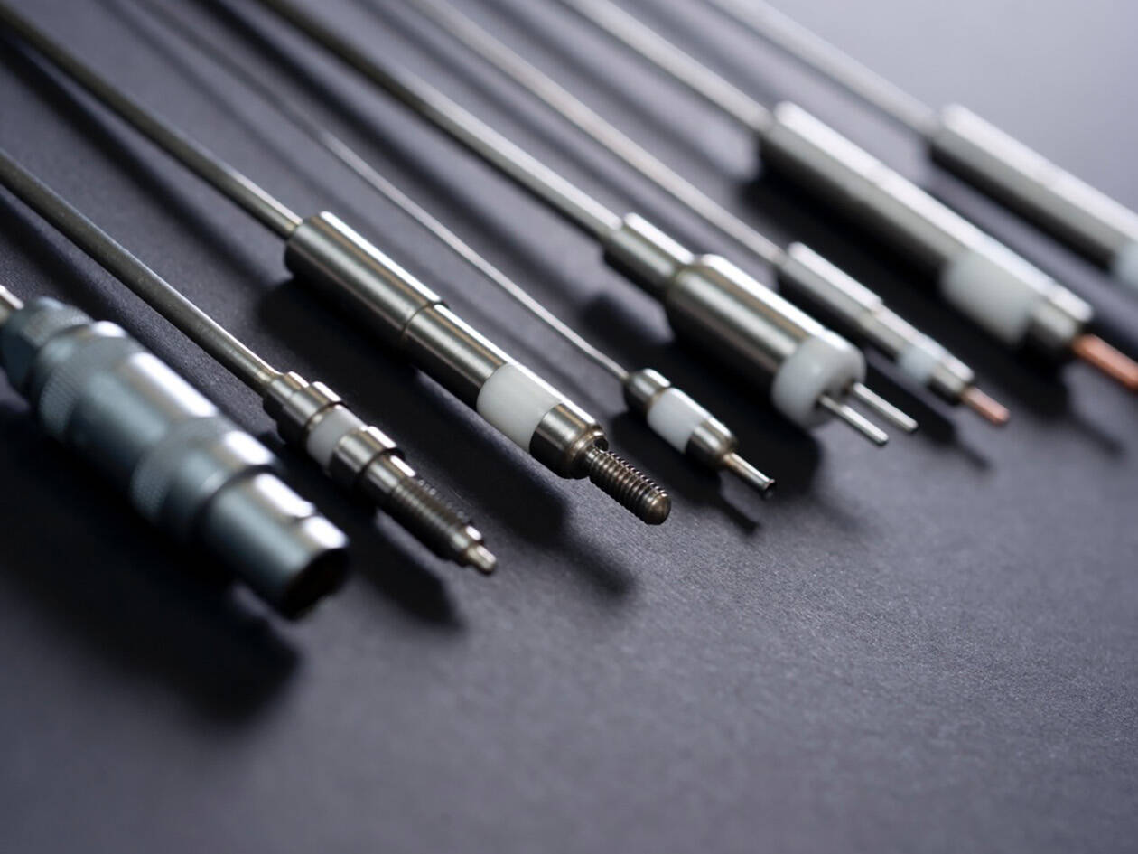
Other connection options are available, including those with open, sealed ends, metal-ceramic electrical connections, or a matching connection cable.
Please feel free to contact us!
More information that might interest you
Installation Methods for Sheath Heating Cables
This is the excerpt for the preview and the preview text at the top
0 Comments8 Minutes
Connections, Installation, and Quality Assurance: From Heating Cables to Reliable Heating Solutions.
This is the excerpt for the preview and the preview text at the top
0 Comments5 Minutes
Single- and two-conductor sheathed cables: The foundation for your heating solution.
Mineral-insulated sheathed heating cables—single-conductor or twin-conductor? This fundamental decision…
0 Comments9 Minutes
Mineral-Insulated Sheathed Heating Cables: Technical Guide for Technicians & Engineers.
In demanding industries such as aerospace, semiconductor technology, and high-end mechanical engineering…
0 Comments10 Minutes
How to Calibrate a Thermocouple Correctly – A Practical Guide.
How to Calibrate Thermocouples Correctly! A practical guide with methods, tips, and…
0 Comments6 Minutes
How to Choose the Right Thermocouple – A Guide for Industry.
Which Thermocouple Is Right for You? A Practical Guide to Types, Materials, &…
0 Comments7 Minutes
Focus on Thermocouples – Why Precise Temperature Measurement Is Important.
Accurate temperature measurement is not just an option—it is essential. Thermocouples are far…
0 Comments5 Minutes